The Engineering and Manufacturing Implications of Wheel Runout Specifications for Vehicle Dynamics and NVH
For B2B buyers and vehicle manufacturers, wheel lateral and radial runout are not merely cosmetic quality metrics but are critical engineering parameters that directly influence vehicle handling stability, steering feel, tire wear, and overall NVH (Noise, Vibration, and Harshness) performance; therefore, specifying and verifying runout tolerances based on the vehicle's dynamic requirements and manufacturing capability is a fundamental step in component sourcing and quality assurance, as uncontrolled runout can lead to systemic vehicle-level issues that are costly to diagnose and rectify post-assembly.
Defining Runout: The Dimensional Foundation of Dynamic Performance
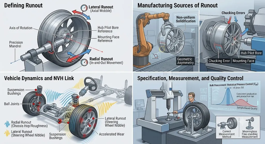
In engineering terms, runout refers to the total indicated variation of a surface as a component rotates about its central axis. For a road wheel, two primary runout specifications are paramount: lateral runout and radial runout. Lateral runout, or side-face runout, is the axial wobble of the wheel's mounting face or outer rim lip. Radial runout is the in-and-out movement of the wheel's bead seat or outer rim surface relative to the axis of rotation. These deviations are not abstract measurements; they are the geometric precursors to dynamic imbalance and non-uniform forces transmitted through the vehicle's suspension.
From a manufacturing perspective, runout is a composite error stemming from multiple stages of the production process. In high-pressure die casting, non-uniform solidification or mold misalignment can create inherent geometric asymmetry in the raw casting. During machining, chucking errors on the CNC lathe, tool wear, or thermal expansion of the workpiece can translate casting imperfections into precise but mislocated machined surfaces, particularly the critical hub pilot bore and mounting face. Even subsequent processes like painting, if the wheel is not fixtured correctly in the curing oven, can induce thermal stress warpage. Therefore, controlling runout is a systemic challenge requiring precision at every stage, not just final inspection.
The Vehicle Dynamics Link: From Geometric Error to Driver Perception
The direct mechanical consequence of excessive runout is the introduction of forced vibrations at frequencies proportional to wheel rotational speed. Lateral runout primarily generates a steering wheel shake or nibble felt through the steering column, as the oscillating axial force creates a fluctuating aligning torque in the suspension. Radial runout, however, produces a vertical vibration felt in the chassis and seat, often perceived as a hop or roughness, especially at highway speeds. These vibrations are not merely annoying; they degrade the driver's perception of vehicle quality and precision.
In real-world applications, the impact is magnified by system interactions. A wheel with runout acts as a non-concentric base for the tire. When mounted, the tire's inherent uniformity variations can compound or, in some cases, partially cancel the wheel's runout, making final assembly matching a complex task. The forced vibrations from runout increase loading on suspension bushings, ball joints, and wheel bearings, potentially accelerating wear. Furthermore, from a vehicle integration standpoint, electronic systems like Anti-lock Braking Systems (ABS) and Electronic Stability Control (ESC) rely on precise wheel speed signals. Severe runout can cause minor fluctuations in the gap between the tone wheel and sensor, though this is a less common failure mode compared to the direct NVH and wear impacts.
Specification and Measurement: Beyond the Basic Tolerance
Industry standards, such as those from SAE or ISO, provide baseline runout tolerances, often in the range of 0.5mm to 1.0mm Total Indicator Reading (TIR) for passenger vehicles. However, for premium OEMs or high-performance applications, specifications are frequently tightened to 0.3mm TIR or less. The critical nuance for B2B buyers is understanding the measurement protocol. Runout must be measured on a precision mandrel that simulates the vehicle hub, with the wheel's pilot bore and mounting face referenced. Measuring a free-standing wheel is meaningless. The measurement location is also specified: lateral runout is typically measured at the outer rim flange, while radial runout is measured at the bead seat or a defined point on the rim well.
However, this advantage diminishes when considering production variance. A supplier may demonstrate a sample wheel with exceptional runout, but the key metric for bulk procurement is the process capability (Cpk) for the production run. A manufacturer with a tightly controlled process (e.g., using on-machine probing for compensation, thermal management of machining, and statistical process control) will deliver consistently low runout across thousands of units. In contrast, a factory relying on final inspection and sorting will have a wider distribution, leading to potential assembly line issues where a wheel at the extreme end of the tolerance band is paired with a tire at its extreme, creating an unacceptable assembly.
Procurement and Quality Assurance Strategy for Bulk Buyers
For commercial vehicle fleets, aftermarket distributors, or OEMs, a strategic approach to runout is essential. First, the specification must be appropriate. Over-specifying (e.g., demanding 0.1mm TIR for a utility vehicle) unnecessarily increases cost without tangible benefit. The specification should be derived from the vehicle platform's NVH targets and suspension design. Second, the Request for Quotation (RFQ) must explicitly detail the measurement method, fixture, and location, and require evidence of statistical process control data, not just sample reports.
During factory audits, buyers should witness runout measurement on the production line and review control charts. They should also audit the wheel-to-hub simulation process; the design of the hub pilot and clamping method can sometimes compensate for minor runout. From a manufacturing perspective, a supplier investing in true horizontal machining centers, where the wheel is machined in one setup, typically achieves better inherent concentricity between features than one using multiple vertical machines requiring re-chucking.
Practical recommendations include implementing incoming quality control (IQC) checks on a statistical sampling basis, correlating wheel runout data with final vehicle NVH test results to refine specifications, and considering a "match-mounting" strategy for high-end applications where wheels and tires are selectively paired at assembly to minimize combined radial force variation. The goal is to treat runout as a controlled, understood variable in the vehicle system, not a surprise defect.
The engineering definitions and vehicle dynamics implications of lateral and radial wheel runout. The primary manufacturing root causes of runout in aluminum alloy wheel production. The link between runout specifications, NVH performance, and component wear. Practical strategies for specifying, measuring, and controlling runout in a B2B procurement context. The limitations of a sample-based quality approach versus statistical process control.
The specific runout tolerances for motorcycle, aerospace, or heavy industrial wheels. The detailed design of hub-centric versus lug-centric mounting systems. The chemistry or metallurgy of aluminum alloys used for wheels. The repair or correction procedures for wheels with excessive runout. The electronic simulation or modeling techniques for NVH prediction.
Wheel lateral and radial runout are critical geometric tolerances originating from manufacturing processes that directly cause vehicle vibrations, affect handling feel, and accelerate tire and suspension wear, necessitating that B2B buyers specify, measure, and control them based on statistical production capability rather than sample performance to ensure consistent vehicle-level quality.